DIY Robocars first year in review

It’s been almost exactly a year since we started the DIY Robocars communities, and the growth has been incredible. Here, in numbers, is what we’ve accomplished over the year.

Displaying your Raspberry Pi IP address on bootup

One of the problems of using RaspberryPi-based cars with Wifi connection is that even if you set them to auto-connect to a certain Wifi access point, you never know what their IP address will be, so you have to waste time search for them on the network. A good way to get around that (and to also display car information without having to SSH in via a terminal) is to mount a screen on the RaspberryPi, as shown above. I like the Adafruit 3.5″ TFT screen, which fits nicely on top of the Pi.

However, it’s not obvious how to get the screen to show your IP address once you connect, especially since the Wifi takes longer to connect than the Pi does to boot up, so any programs that run at bootup won’t be able to get the IP.  I searched for a while and then finally gave up and wrote it from scratch.  Here’s what you need to do:

First, edit the “crontab” file, which automatically runs programs at launch or at any frequency.  At the the command prompt, type “crontab -e”, which will ask you to select an editor. Select Nano, and add this line at the bottom of the file:

@reboot sleep 10; sudo python ip.py > /dev/tty1

Let me explain what that line does:

  1. The “@reboot” part says to do this once after every reboot.
  2. The “sleep 10;” part says to delay for ten seconds to give the Wifi time to connect.
  3. The “sudo python ip.py” part says to run a Python script called ip.py, which we’ll add next
  4. The “> /dev/tty1” part says to send the text output to the screen, which is called tty1.

Now we have to create the “ip.py” file that will display the IP address.  Type “sudo nano ip.py” to create the file and paste this:

import os
import socket
import fcntl
import struct

def get_ip_address(ifname):
 s = socket.socket(socket.AF_INET, socket.SOCK_DGRAM)
 return socket.inet_ntoa(fcntl.ioctl(
 s.fileno(),
 0x8915, # SIOCGIFADDR
 struct.pack('256s', ifname[:15])
 )[20:24])

print("Wifi: ", get_ip_address('wlan0'))
print("Ethernet: ", get_ip_address('eth0'))

That’s it. Now the screen should show both the Wifi and Ethernet (if connected) addresses on bootup.

A “Minimum Viable Racer” for OpenMV

This is the cheapest good computer vision autonomous car you can make — less than $90! It uses the fantastic OpenMV camera, with its easy-to-use software and IDE, as well as a low-cost chassis that is fast enough for student use. It can follow lanes of any color, objects, faces and even other cars. It’s as close to a self-driving Tesla as you’re going to get for less than $100 😉

It’s perfect for student competitions, where a number of cars can be built and raced against each other in an afternoon.  NEW BONUS: If you want to move to a more advanced linear-regression code, instructions are here

Parts:

Optional:

Total: $85 to $120, depending on which options you choose and whether you can 3D print your own parts.

The code is optimized for standard RGB tracks, which can be made with tape.

Instructions:

  • 1) Cut two 12″ lengths of black and red wire pairs, and strip 1/4″ from each end. These will be the wires to connect your motors to the OpenMV board.
  • 2) Assemble the rover kit as per the instructions, soldering the wire you just cut to the motor terminals (for consistency, solder the red wires to the terminals furthest from the chassis and the black wires to the terminals closest to the chassis, as shown in the picture below). We can always switch them at the motor driver side later, but this will make it easier not to get confused). Don’t overtighten the motor mounts; they’re fragile. If you break one, you can 3D print a replacement with this file, buy them from Shapeways here, or just cut it out of 3.5mm plywood.

  • 3) As for the rocker on/off switch, just snap it into place on the chassis, then snip the red battery wire an inch from the battery case and solder that to one of the switch’s terminals, then solder the rest of the wire to the other terminal as shown here:

  • 4) 3D print (or have printed at Shapeways) the camera mount. Attach it to the chassis with screws as shown in the pictures above.
  • 5) Screw the OpenMV camera to the mount as shown:

  • 6) Attach the motor and battery wires to the OpenMV motor shield as shown below. Once you’re done, carefully insert it into the connectors at the back of the OpenMV cam.

  • 7) Load the code into the OpenMV IDE, plug your USB cable into the OpenMV board and run it while it’s looking at a green object (it defaults to following green, although that’s easy to change to any other color in the IDE). (Make sure your rover is powered on with batteries in). If one of the motors is turning backwards, just swap the wires from that motor going into the motor controller.
  • Here’s how to test it and ensure it’s working:

  • 8) If the rover tends to turn one way or the other, you can correct the “center” position by modifying the value in this line:
steering_center = 30  # set to your car servo's center point
  • 9) Once you’re happy with the way the code is working, you can load it so it will start automatically even if a USB cable is not connected by selecting “Save open script to OpenMV Cam” in the Tools menu, as shown:


Code tweaking tips

If you want it to follow a different color, just change this number in the code:

threshold_index = 1
# 0 for red, 1 for green, 2 for blue

If you want to tune it for another color, or adjust it so it follows the color you’ve selected better for the specific tape and lighting you’ve got, use the IDE’s built-in Threshold Editor (Tools/Machines/Vision/Threshold Editor) and add a threshold set for the color (or replace one of the generic thresholds) that you want in this section of the code:

thresholds = [(0, 100, -1, 127, -25, 127), # generic_red_thresholds
              (0, 100, -87, 18, -128, 33), # generic_green_thresholds
              (0, 100, -128, -10, -128, 51)] # generic_blue_thresholds
# You may pass up to 16 thresholds above. However, it's not really possible to segment any
# scene with 16 thresholds before color thresholds start to overlap heavily.

In the below example, I’ve tuned it to look for red lanes. So I’d copy the “(0,100,30,127,-128,127)” and replace the generic red threshold numbers above with that.  Then I’d change the line above that to “threshold_index = 0”, so it would look for the first threshold in the list, which is red (lists are “zero-based”, so they start at zero).

When you’re done, the IDE will show it tracking a color lane like the above (the lowest rectangular “region of interest” — ROI — is weighted highest, with the other two weighted less). You can modify the ROIs by dragging boxes on the screen to show the region you want to identify, and then give it a weighting as show here:

# Each ROI is (x, y, w, h). The line detection algorithm will try to find the
# centroid of the largest blob in each ROI. The x position of the centroids
# will then be averaged with different weights where the most weight is assigned
# to the ROI near the bottom of the image and less to the next ROI and so on.
ROIS = [ # [ROI, weight]
(38,1,90,38, 0.4),
(35,40,109,43,0.2),
(0,79,160,41,0.6)
]

Latest race results show both CV and CNN improving, will beat humans soon

Here’s the latest data from the DIY Robocar monthly race series, thanks to our Track Master, Adam Conway.

A few things to note about these results:

  1. The gap between traditional computer vision techniques (“CV”) and convolutional neural network machine learning (“ML”, also known as AI/deep learning/CNN) is shrinking.
  2. The best of both will probably beat the best human drivers by the end of the year
  3. This is in some sense a proxy war for the philosophical debate between the two approaches that is playing out in the full-sized self-driving car industry. Google/Waymo represents the ML-centric approach, while Tesla represents the CV-centric approach.
  4. In both CV and ML, the top teams are using custom code. The two standard platforms — Donkey for ML and OpenMV for CV — are not yet beating the custom rigs. But over time, with more adoptions and collective development, there’s no reason why they can’t.
  5. Everyone is getting better fast!


Roll your own local DIY Robocars group

Want to set up a DIY Robocars race/hack event in your own town, like the folks in DC, Austin, NYC and elsewhere have? Go for it — it’s easy!

All you need is a room that’s big enough (the standard track is about 30m x 20m, although you can use any size you want that will fit in your room) and some tape (or paint if you want to make it permanent).

For the track:

  • If you’re using tape, gaffers tape is best
  • If you’re using paint, “satin”-texture latex floor paint is best. Apply with a 3″ roller.

The dimensions of the standard track are here, but again feel free to modify as you’d like.

Once you have a room secured, do the following:

  1. Use Meetup to organize the event.
  2. Free free to use the DIY Robocars branding on your own Meetup page. The graphics are here. Just use what you want and please link back to the mothership on your own site
  3. Want to add more challenge, with obstacles and/or other cars? Here are some tips. Of go all the way to the Official Rules!
  4. Want to use a RGB track? Here are instructions on how to make that.
  5. Comment here and we’ll add you to the master list of local meetup groups around the world.

A few tips:

  • Train in the morning, break for pizza lunch, race at 1:00
  • Saturdays are best
  • If you have or can borrow a PA system, that will help with the race announcing
  • Try to keep it fun, low pressure and welcoming to people of all skills.  Today’s casual spectator can be tomorrow’s competitor if you spark their imagination!

Comparing low-cost 2D scanning Lidars

It’s now possible to buy small scanning 2D Lidars for less than $400 these days, which is pretty amazing, since they were as much as $30,000 a few years ago. But how good are they for small autonomous vehicles?

I put two to the test: the RP Lidar A2 (left above) and the Scanse Sweep (right). The RP Lidar A2 is the second lidar from Slamtec, a Chinese company with a good track record. Sweep is the first lidar from Scanse, a US company, and was a Kickstarter project based on the Lidar-Lite 3 1D laser range finder unit that was also a Kickstarter project a few years ago (I was an adviser for that) and is now part of Garmin.

The good news is that both work. But in practice, the difference between them become very stark, with the biggest being the four times higher resolution of the RP Lidar A2 (4,000 points per second, versus Sweep’s 1,000), which makes it actually useful outdoors in a way that Sweep is not. Read on for the details.

First, here are the basic spec comparisons:

Scanse SweepRP Lidar A2
Samples/sec10004000
Tested range~4-5m outdoors, ~12m indoors (much less than claimed range of 40m)~4-5m outdoors, ~14-16m indoors (much more than claimed range of 6m)
Scan rateUp to 10HzUp to 15Hz
Angular resolution3.6 degrees0.9 degrees
Height2.5cm1.5cm
ROS integrationyesyes
Python driveryesyes
Cost$350$379 (for 2 or more), $450 (for 1)

Bottom line: RP Lidar A2 is smaller, much higher resolution, and better range indoors (it’s notable that the real-world RP Lidar performance was above the stated specs, while the Scanse performance was below its stated specs). The Scanse desktop visualization software is better, with lots of cool options such as line detection and point grouping, but in practice you won’t use it since you’ll just be reading the data via Python in your own code. Sadly the Scanse code that does those cool things does not appear to be exposed as libraries or APIs that you can use yourself.  [Update: Scanse has now released those libraries here]

In short, I recommend the RP Lidar A2.

I tested them both in small autonomous cars, as shown below (RP Lidar at left). Both were tested on a sunny day for the outdoors test, in exactly the same way.

Both have desktop apps that allow you to visualize the data. Here’s a video of the the two head-to-head scanning the same room (RP Lidar is the window on the right)

You can see difference in resolution pretty clearly in that video: the RP Lidar just has four times as many points, and thus four times higher angular resolution. That means it can not only see smaller objects at a distance, but the objects it does see have four times as many data points, making it much easier to differentiate them from background noise.

As far as using them with our RaspberryPi autonomous car software, it’s a pretty straightforward process of plugging them into the RaspberryPi via the USB port (the RP Lidar should be powered separately, see the notes below) and reading the data with Python.  My code for doing this is in my Github repository here.  We haven’t decided how best to integrate this data with our computer vision and neural network code, but we’re working on that now — watch this space.

The one thing that seems clear is that ROS, which has support from both lidars, is probably overkill for the simple obstacle avoidance we want the lidars for in a track racing context. It’s designed for SLAM (simultaneous location and mapping), which works too slowly for racing. So we’re implementing our own lidar integration that’s designed to just spot obstacles and avoid them.

Finally although these units are amazing and the field is making tremendous progress, we still have a long way to go. Just watch the video below to put our 2D units in context. 3D lidar is astounding, and a few years from now we may see 3D solid state lidar at the same sub-$1,000 price we can now get 2D lidar for.


A few tips and additional notes:

  1. Yes, it’s true that a 2D scanning lidar is just a 1D range finder on a spinning platform, but DO NOT TRY TO DO THIS YOURSELF. I’ve been there, done that, and integrating the data reliably in motion is non-trivial. Pay the extra $200 and get a proper scanning one.
  2. For the RPLidar, to use it with a RaspberryPi, you’ll need to power it separately. It uses a 5v power and has a tiny jack. These are the plugs that fit it.
  3. Of course you can always buy an old Neato unit (cannibalized from their vacuum cleaners) for $120 from eBay or Amazon. They’re pretty well supported with open source code but have much lower resolution than modern units. I think their time is gone — move on the RP Lidar instead.
  4. You can use an OpenMV computer vision module as a poor man’s Lidar. Total cost: $70!
  5. There’s a project to convert Scanse to a full 3D spherical scanner. The scanning rate will be way too slow for motion, but you could scan a room this way.

Two ways to handle control loops in Python

In robot control systems, it’s common to have an “inner loop” that controls basic motion and an “outer loop” that does higher level control, such as navigation.  (You can have even higher level control, such as mission planning, above that but we’ll concentrate on the first two for now).  In the case of drones, for example, the inner loop runs very fast (400 times a second, or 400 Hz, is typical) for precise control of basic stabilization. The outer navigation loop, on the other hand, can run more slowly — typically 10 times a second (10 Hz), which is the speed at which standard GPS modules update their position.

Ideally, you have both these loops running at the same time, using multithreading on Linux or a real-time operating system. But that can be somewhat intimidating to program and there are some gotchas that you have to watch out for when you’re running multiple threads, such as race conditions.

Until recently, Python didn’t have such “concurrancy” built-in, and you had to use special libraries to do this. But starting with 3.5, this sort of asynchronous code execution was vastly improved with the native “asyncIO” module, which is well explained here.  This should allow you to run multiple loops running at different speed simultaneously by using “coroutines“, without much programming overhead and risky clashes.  To try this out, I did the following experiment.

Let’s say you want to run and inner loop at 10Hz and an outer loop at 1Hz. In regular Python you’d code it like this:

import time

def tenhz():
  time1 = time.time()
  print ("Ten Hz")
  while True:
    if time.time() > (time1 + 0.1):  # check to see if a tenth of a second has passed
      break
  
def onehz():
  time1 = time.time()
  print ("One Hz")
  while True:
    tenhz()
    if time.time() > (time1 + 1):  # check to see if a second has passed
      break
  
while True:
  print("root")
  onehz()

That works — the “tenhz()” function will run ten times  a second, and the “onehz()” function will run once a second — but the problem is that the two loops won’t run simultaneously.  While the tenhz() function is running, the onehz() function is not, and vice versa. One blocks the other.

With Python’s new AsyncIO concurrency feature, you can effectively have the two running at the same time — no blocking — in separate threads without a lot of fuss.  Here’s how those same loops look programmed for asynchronous operation (thanks to this guide as a starter).

import time
import asyncio

start = time.time()

def tic():
    return 'at %1.1f seconds' % (time.time() - start)

async def gr1():
    # Busy waits for a tenth of a second, but we don't want to stick around...
    print('10Hz loop started work: {}'.format(tic()))
    time1 = time.time() 
    while True:
      # do some work here
      await asyncio.sleep(0)
      if time.time() > time1 + 0.1:
        print('10Hz loop ended work: {}'.format(tic()))
        time1 = time.time() 

async def gr2():
    # Busy waits for a second, but we don't want to stick around...
    print('1 Hz loop started work: {}'.format(tic()))
    time2 = time.time()
    while True:
      # do some work here
      await asyncio.sleep(0)
      if time.time() > time2 + 1:
        print('1 Hz loop ended work: {}'.format(tic()))
        time2 = time.time()

async def gr3():
    print("Let's do some stuff while the coroutines are blocked, {}".format(tic()))
    time3 = time.time()
    while True:
      # do some work here
      if time.time() > time3 + 20:
        print("Done!")
      await asyncio.sleep(0)

ioloop = asyncio.get_event_loop()
tasks = [
    ioloop.create_task(gr1()),
    ioloop.create_task(gr2()),
    ioloop.create_task(gr3())
]
ioloop.run_until_complete(asyncio.wait(tasks))
ioloop.close()


Much better! Now you can insert your own code in those loop and not worry about one blocking the other.  Yay Python 3.5!


First experiments with JeVois computer vision module

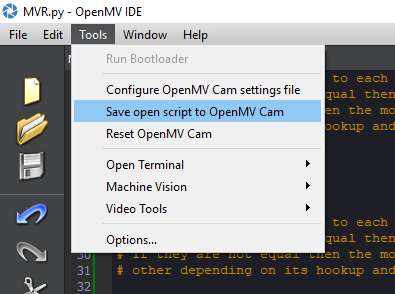
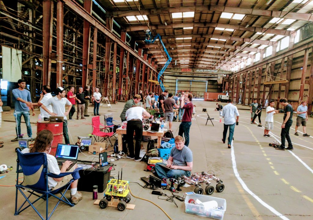
I’m a huge fan of the OpenMV cam, which is a very neat $65 integrated camera and processor with sophisticated built-in computer vision libraries, a Micopython interpreter, and a very slick IDE (a car powered entirely by it came in 2nd in the Thunderhill DIY Robocars race). Now there is a competitor on the block, Jevois, which offers even more power and a lower cost. I’ve now spent a week with it and can report back on how it compares.

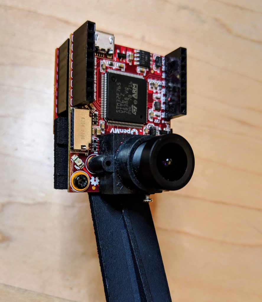
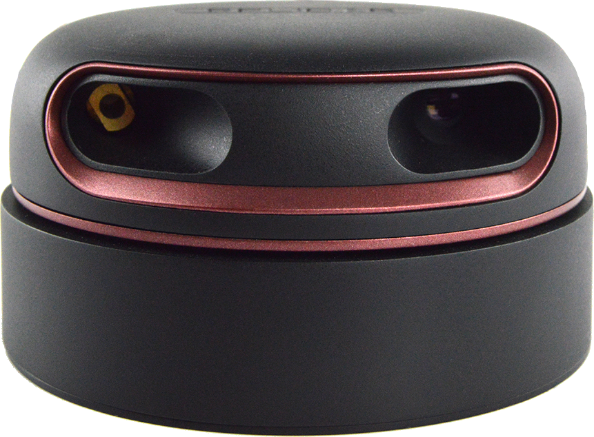
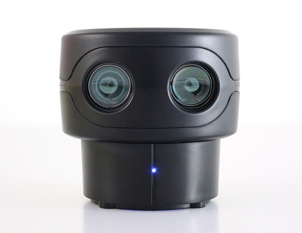
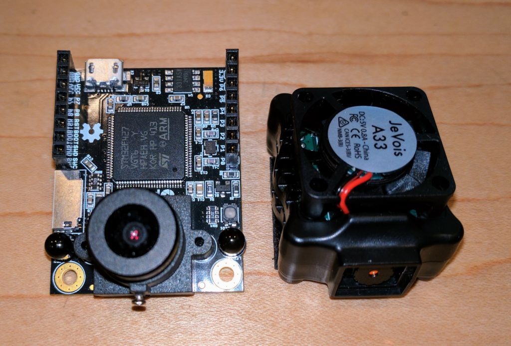
In terms of form factor, it’s a bit smaller than OpenMV

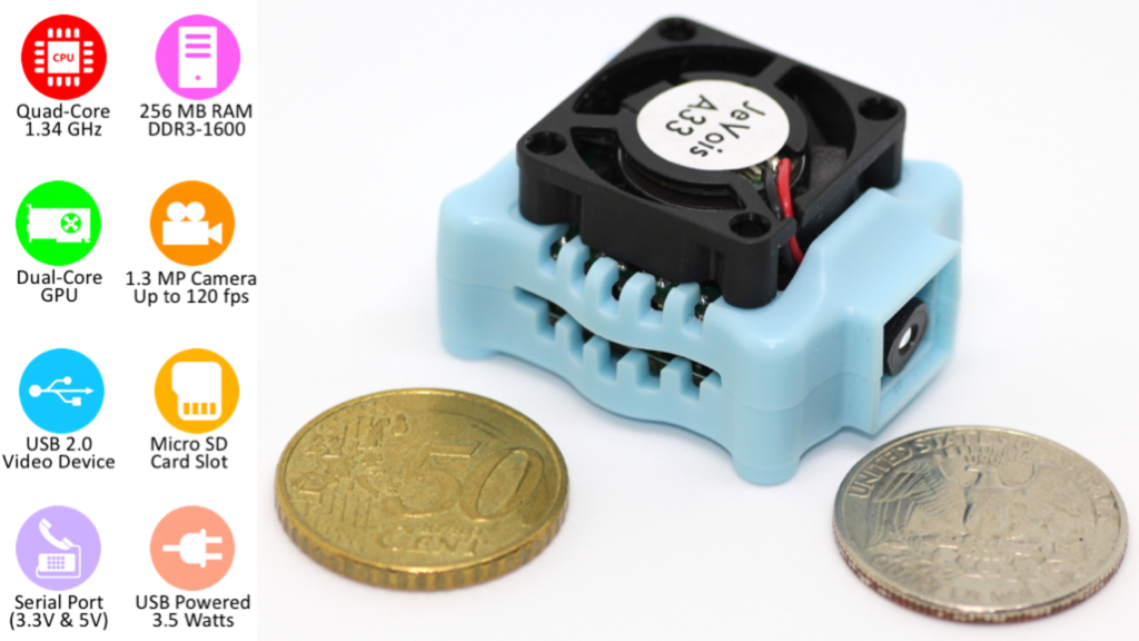
Here’s a quick feature comparison:

OpenMVJevois
Camera320x240, with good 2.8mm standard lens (can be switched to wide angle or IR)320x240, no removable lens
Processor216 Mhz M71.34 Ghz A7, with GPU
I/O3 PWM, Serial, I2C, 1 ADC, 1 DAC, USBSerial, USB
Expansion boardsWifi, LCD screen, proto board, thermal camera(none)
OSMicropythonLinux
Power consumption140 ma700-1,000 ma
IDEQT Creator based custom IDE (Mac, Windows, Linux)(none)
Memory512KB RAM, 1 MB flash, SD card256MB RAM, SD card
Price$65$50

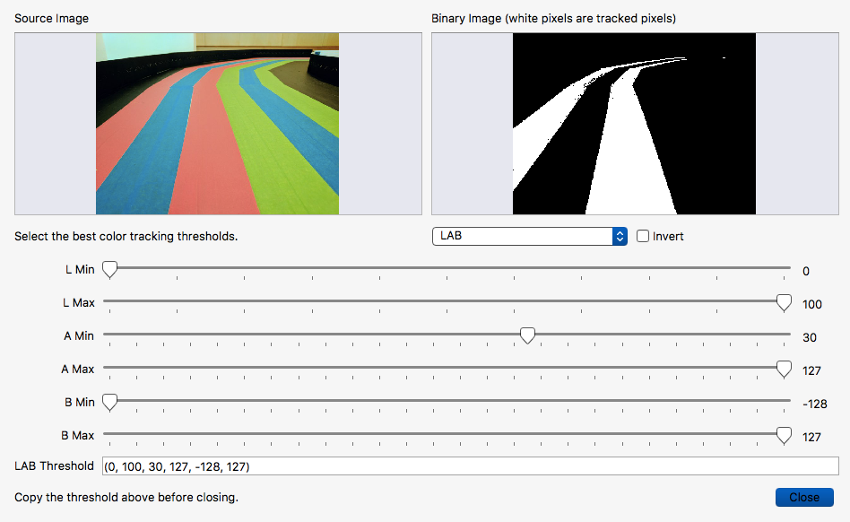
Both come with a full suite of standard computer vision libraries and examples. (OpenMV’s libraries are here and examples are here; Jevois’s libraries are here and examples are here). Both are well supported on the software side and have good communities. Jevois derives from the Jevois software framework that came out of academic work at USC. OpenMV is the work of small team of very smart computer vision experts, but benefits from the large Micropython community.

Basically, the Jevois board is more powerful, but the OpenMV board is a lot easier to use and more flexible, mostly due to its awesome IDE and native Micropython environment. Both can do our job of driving an autonomous car, so it’s just a question of which board is easier to develop on.  Also, why would you get one of these instead of a RaspberryPi 3 and camera, which doesn’t cost much more?

For OpenMV, the reason to use it over RaspberryPi is simply that it’s easier. It’s got a great IDE that works over USB or Wifi that makes interactive use fun, it’s all in one board, and it can drive servos and read sensors without any additional add-on boards. Although the performance is not quite as good as RaspberryPi and it can’t run standard Linux packages like TensorFlow, the included CV libraries are well optimized to make the most of the hardware, and for basic computer vision the included libraries handle most of what you’ll want. (If you want to use neural networks, use the RaspberryPi — these are just computer vision boards).

For Jevois, the reason to use it over RaspberryPi is not as clear. It is potentially more powerful that a RasperrryPi at computer vision, thanks to the built-in GPU, but in practice it seems to perform about the same.  But more importantly, it’s much harder to use.  After spending a week getting it up and running, I think the only reason to use it over RaspberryPi is in cases where you need a very small, integrated package and can use the built-in modules pretty much as they are without much additional programming.
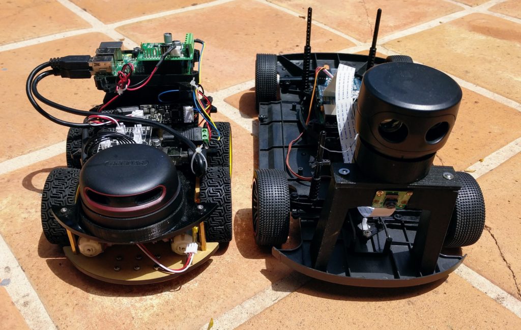
My testbed

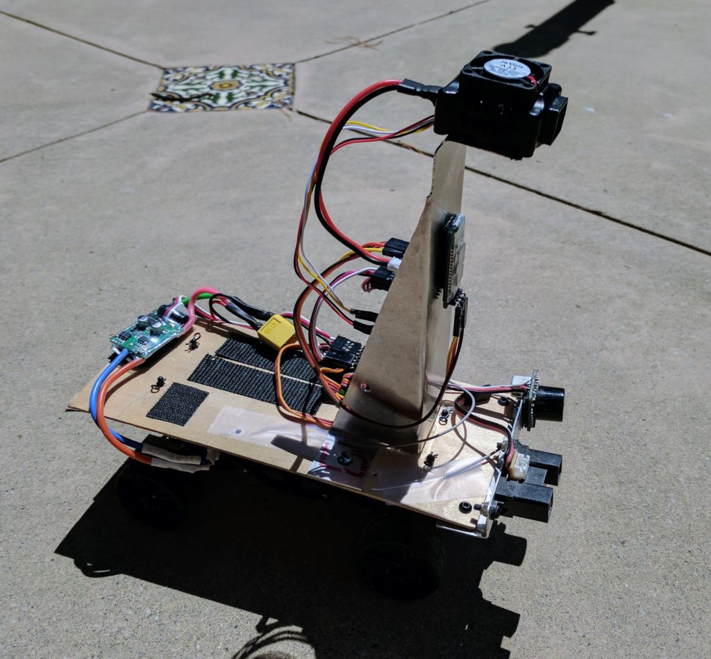
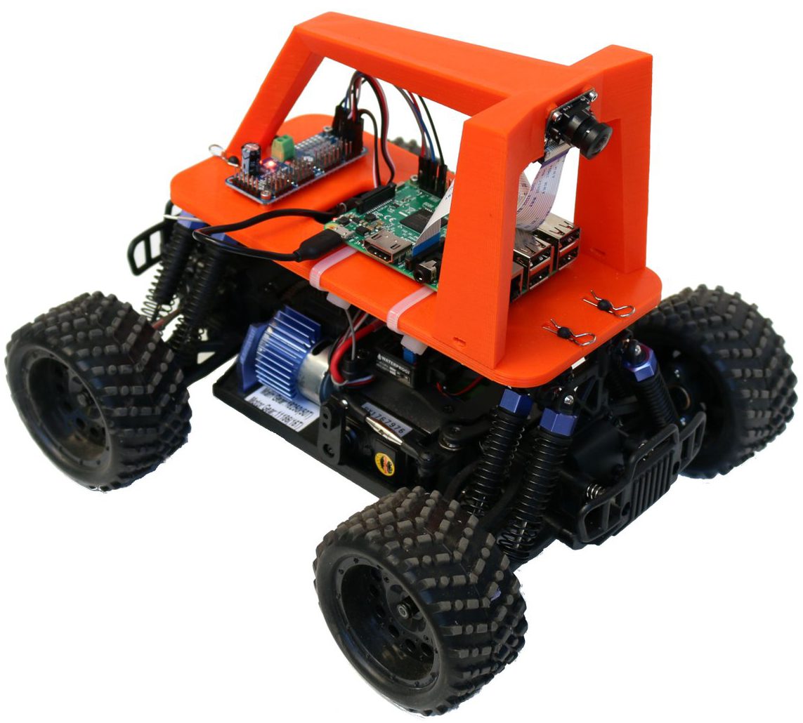
I built a small rover to use Jevois’s RoadNavigation function, using a cheap RC car chassis and some plywood and aluminum. The software uses a “vanishing point” algorithm to see the road ahead and keep the rover on it.

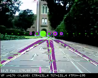
The module works very well when you plug it into a PC via USB and use a video app to test the computer vision modules, such as looking at a picture of a road. What’s much harder, however, is using it in the real world, in an embedded environment where you need to read the data, not just look at the cool on-screen lines.

To do that, you need to do a lot of work on both hardware and software:

Hardware:

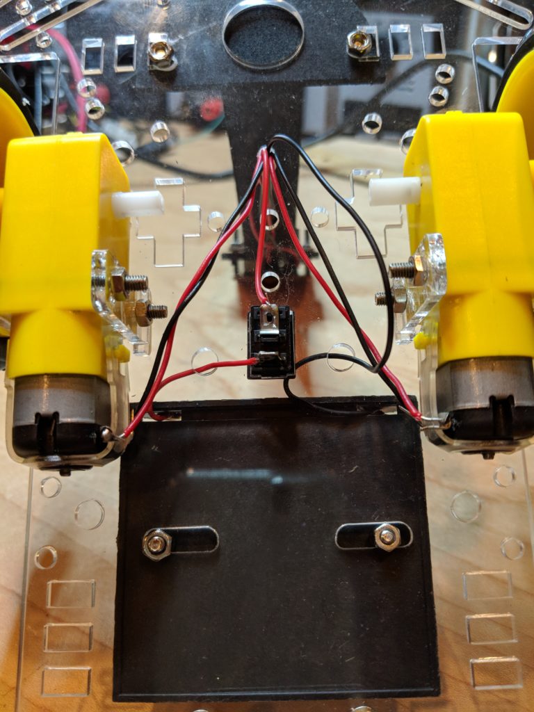
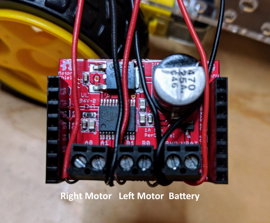
You’ll need to get the Jevois talking to an Arduino, which will do the actual control of the car’s servos and motors. You can do that by adapting the included serial cable to connect to an Arduino.  A tutorial is here, but in practice it’s a good bit harder than that.  In my case, I used an Arduino Mini Pro running Software Serial to talk to the Jevois, so I could program and monitor the Arduino via a FTDI cable or Bluetooth bridge while it was communicating with the Jevois. I also created a custom PCB to attach the Arduino Mini to and break out pins for servos and sensors, although that’s not necessary if you use a regular Arduino and don’t mind a lot of wires hang off it. My Arduino code for this is here.

You’ll also need to power the Jevois via a Mini USB cable. I created my own using these connectors.  The regular ESC that drives your car’s motor will not provide enough power for the JeVois, so I used a stand-alone power regulator like this one.

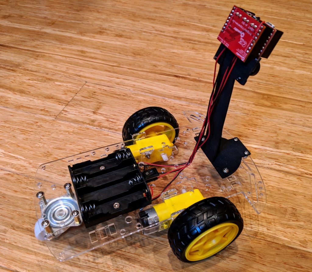
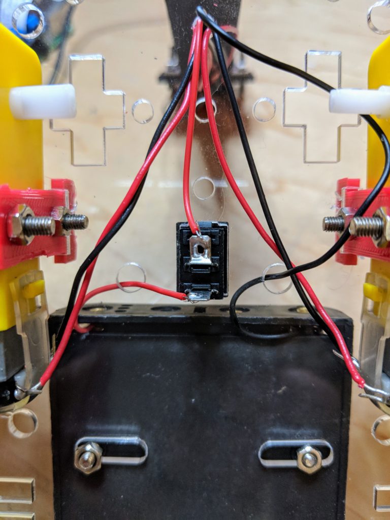
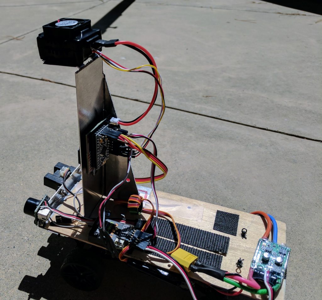
Here’s another shot of the completed car from the back, which shows the Arduino connection. You’ll note that it also has sonar and IR sensors at the front; those are not used now.

The hard part was the software. Basically, the way to use Jevois is primarily through modifying configuration files that are on the module’s SD card.  The three necessary ones are here, but I’ll explain the key elements in the next section:

Initscript.cfg:

setmapping 1  # this selects the module that's assigned to Mode 1, which happens to be a video setting called "YUYV 320x240 30.0 fps"
setpar serlog None # this tells it not to save a log file
setpar serout Hard # this tells it to send data to the serial port
streamon # this tells the module to start, even though the board is not connected to USB

Params.cfg:

serialdev=/dev/ttyS0  # this tells it to use the serial port
serial:baudrate=38400 # this sets the baud rate to 38400
serial:linestyle=LF # this sets the line endings to a LF, which make it easier to parse

Videomappings.cfg:

NONE 0 0 0 YUYV 320 240 30.0 JeVois RoadNavigation # this is the key line. It assigns the 320x240 30fps video mode with no USB output to the RoadNavigation module

This last one is the most confusing, but the basics are that for arcane reasons involving not having a proper IDE and having relatively bare-bones video support, the only way you can command the Jevois module from a computer is by commanding changes in video mode. So all modes are mapped to a virtual video mode (confusingly, even if that’s not actually the video mode that it’s using), and the way to tell the board which mode you want it to boot up into is by assigning that module to the video mode number you’re calling in the Initscript.cfg, which runs on startup.

This all took forever to figure out, and needed a lot of help from the team in the forums.  But now I’ve done it for you, so you just need to copy the files from here onto your SD card and it should work right out of the box.

In my opinion, this is too hard for beginners. The most perplexing thing about Jevois is that it runs Linux, but there’s no way to get to the Linux command line that I can find.  If you could get to Linux via the USB cable (rather than just a weird command input parser that’s a lot like the old modem’s “AT” command set), you’d be able to script this powerful board properly and otherwise use modern programming tools. But as it is, this is a very fiddly matter of taking out the SD card and editing configuration files on a Linux PC,  guessing at parameters, sticking it back into the Jevois board, powering it up and praying.

The Jevois software project is very mature and powerful, so I have no doubt that this more user-friendly exposure of its Linux heart and deep AI and CV libraries can be done. But right now the Jevois computer vision board feels like a cool demo (and an incredibly cheap computer vision computer) but not worth the hassle to use for real work when you can do so much more with a RaspberryPi in much less development time.  Perhaps the next version will improve this.

[UPDATE: JeVois has now added the ability to read and write files on the SD card via USB, as well as Python 3.5 support, which is definitely a step in the right direction]


The Path to Wheel to Wheel Racing

In the past 5 months we have seen performance improve greatly in our 1/10 scale “fastest lap” race format.  When we started out cars were traveling about 1 m/s with the most recent races we see cars traveling at 3 m/s, with the fastest human drivers averaging around 8 m/s.  With the next set of innovations,  we expect cars to move into the 5-6 m/s range, closing the gap with human drivers.  While this speed improvement does require introduction of new methods, we will be moving into a period of refinement rather than invention.  So it is time to shake things up.    

In order to encourage the next set of innovations,  we are going change up the rules and lay out a timeline for wheel to wheel racing.  This will happen over a course of months with intermediate milestones.  To simplify this objective we will be using AR tags (specifically AprilTags) to identify the cars.  This focuses the challenge on localization, and path planning rather than vehicle identification.  Finally for those who want to focus solely on single lap performance, we will continue to have the single lap race.

Example AprilTag AR Tag

There will be two races for the 1/10 scale cars:

The first race will be a single timed lap, shortest lap time wins, gets pole position and first seed for the wheel to wheel race.  This is similar to our existing race.

The second race will be a wheel to wheel event and will race two cars at a time, if there are more than two cars participating the cars will be put into a seeded ladder.  Each car will have a 10×10 cm 36h11 AprilTag attached to the back of the car vertically and within 3cm of the ground.   Tags must remain vertical within +/- 10 degrees during the race.  Minor collisions are to be expected, however a car that causes a collision that prevents a competitor from completing the race is grounds for forfeit or re-race as determined by the track master or other designated judge.  The wheel to wheel race will be 3 laps.

Timeline:

  • May 13 race:  We will have AprilTags around to show to people and Andy Sloane will have a tech demo and sample code ready.
  • June Race:  In addition to our standard race, we will run an initial exhibition race where we will put stationary AprilTags on the track as obstacles.  Cars that can avoid the obstacles and get around the track at the fastest speed win.
  • July Race: Exhibition Wheel to Wheel!  This will be our first Wheel to wheel race.  Racers should be able to identify other cars and avoid them, but it is also a chance to test code and share techniques.
  • August Race: First real wheel to wheel race!

Note: Timeline may be adjusted based how well we hit our milestones.

Request for comments.  Please go to the DIYRobocars forum to discuss and comment.  These rules are not locked in stone and I would like feedback.  Please try to provide feedback soon, I would like to close on this by 5/15