In the past year there’s been an explosion of good, cheap depth sensors, from low-cost Lidars to “depth cameras” with stereo vision and laser projection. It’s now easy to augment or even replace computer vision with depth sensing in DIY robocars, just like most full-size self-driving cars do. Intel has been leading a lot of this work with its great Realsense series of depth sensing and tracking cameras, which are under $200 and have a solid SDK and often built-in processing. This post is the latest in my tutorials in using them (a previous post on using the Realsense T265 tracking camera is here).
One of the ways to compare depth sensing cameras with Lidar (2D or 2.5D) is to use them to navigate a maze. There are lots of ways to navigate mazes, including very simple depth sensors such as an array of ultrasonic (sonar) or 1D laser range sensors (“time of flight”), but the common factor between a Lidar unit and a depth sensing camera is that they do more than those 1D sensors: they both return an array of pixels or points with depth information across a sweep of area around the vehicle.
The difference between these two kinds of sensors is that a spinning Lidar unit can potentially show those points around a full 360-degree disc. A depth camera, on the other hand, can typically can only see a rectangular area forwards like a solid state Lidar, with a horizontal spread of around 90 degrees. Unlike most solid state Lidars, however, a depth camera typically has has a much wider vertical spread (also around 90 degrees).
Camera tend to have shorter range than Lidar (10m max, compared to 20-30m max for low-cost Lidar) and lose precision the further they are from an object. On the other hand, depth camera are much higher resolution (a million points per second for a camera vs about 10,000 for a low-cost Lidar).
Cameras are also much cheaper: $180 for the RealSense 435 versus around $840 for the cheapest solid state Lidar, a Benewake CE30-A.
Here’s a table that summarizes the above:
| 2D Spinning Lidar (RPLidar A1) | 2.5D Solid State Lidar (Benawake CE30-C) | 3D Depth Camera (Intel Realsense 435) | |
| Cost | $120 | $959 | $179 |
| Resolution | 8k points/sec | 150k points/sec | 1m points/sec |
| Range | 12m | 3-4m | 9-10m |
| Coverage | 360 x 1 degrees | 132 x 9 degrees | 87 x 58 degrees |
The purpose of this experiment was to see whether the Realsense Depth Camera could do as a well as a laser. Spoiler: it can! (see below)
A note about the computer I used for this, which was a Raspberry Pi 3. It doesn’t have enough power to really take advantage of the high speed and large data return from the Realsense sensors. However, I used it because I wanted to use the new Sphero RVR as the chassis, since it does a nice job of making all the motor driver and heading control simple and automatic, thanks to an internal gyroscope and PID-driven motor controller with encoders — you just tell it what direction to go and goes there, straight as an arrow.
The RVR can power your onboard computer with 5v via USB (it communicates with the computer via a separate serial cable). That limited me to computers that could be powered at 5v, which includes the Raspberry Pi series, Odroids and the Jetson Nano. However, there is also a low-cost x86 single-board computer (SBC) that Intel recommends, call the UP Board, and that runs on 5V, too. So if I was starting this again and I’d use that instead, since it should be able to install the Realsense SDK with a simple “sudo apt install” and “pip install”.
The second problem with the Rpi is that the Realsense SDK only works on Ubuntu (as well as Windows, although that wasn’t an option here). Although there is a version of Ubuntu (Ubuntu Mate) that works with the Raspberry Pi 3, support for the more powerful Raspberry Pi 4 is incomplete, and I couldn’t get Realsense to work on it. So Raspberry Pi 3 it was.
Compiling the Realsense SDK (librealsense) on the Rpi 3 can take a full day (unattended, thankfully) and you have to do it again every time Intel releases a new version, so that’s a bit of a hassle. So lesson learned: if you have an UP Board, use that. But if you happen to have a RPi 3, it will work, just more slowly.
Software
Enough of the hardware: let’s talk about the software! My approach to the maze-following task was to basically look at all the depth signatures in front of the car, with as wide a view as possible and a vertical “region of interest” (ROI) set as above the ground and not far above the height of the maze walls. I figure out which path has obstacles furthest away (ie, is most open) and head that way — basically go to where the path is clearest ahead. (This is mathematically the same as avoiding the areas where the obstacles are closest).
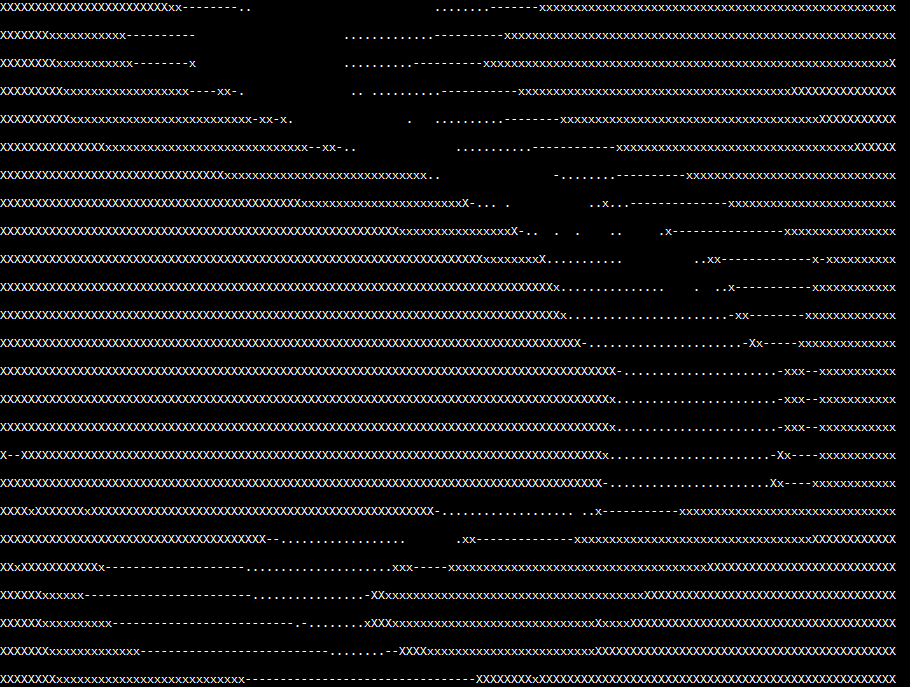
In my Python code, I do that the following way. Thirty times a second, the Realsense sensor sends me a depth map (640×480 pixels). To save processing time, I read every fifth pixel from left to right for each scan line within my vertical ROI (in this case from line 220 to 280), creating 128 “stacks”, each of which contains 60 vertical pixels, which is about 8,000 points in total. I then average the values within each stack and display them in a serial terminal in a crude character-based display like this (the smaller dots are the more distant obstacles, ie, the clear path ahead):

I then bin them in blocks of ten of these stacks, for a total of 13 blocks. Each block then gets an average and then I steer towards the block with the highest average (furthest distance). If I get stuck in a corner due to the relatively narrow field of view of the Realsense depth camera (“corner” = all visible directions have obstacles less than 0.75 meters away), I stop and rotate in 15-degree increments until I can see a clear path ahead.
It’s pretty simple but it works most of the time. That said, a simple 360-degree 2D lidar would do even better in this course, since it would be able to see the best open path at all times without having to stop and rotate. For that matter, a simple sonar “stay 10 cm from the right wall” method would work equally well in this idealized environment (but not in a real-world one). So perhaps a maze is not the best test of the Realsense sensors – a more open-world environment where they are used for obstacle detection and avoidance, not path following, would show off their advantages better.
Lessons learned:
- Don’t use Raspberry Pis for Realsense sensors. Use Up boards or Jetson Nanos instead
- Depth cameras are as good and way cheaper than solid state Lidar for short-range sensing
- That said, 360-degree sensing is better than 90-degree sensing
- The Sphero RVR platform is easy to use. It just works!

Hey Chris,
Good to see thise article. I’m also an Rvr owner. I’ve been reverse engineering the serial protocol into C++ and my target piggy back board is an Up Board. Got an earlier RealSense, forge which model, that I want to use for experiments.
Good to see the Rvr mentioned. The hacker community needs to be made aware of it.
“Don’t use Raspberry Pis for Realsense sensors. Use Up boards or Jetson Nanos instead”
This is not entirely true IMO. A Pi is fully sufficient for T265, e.g. if only poses are used.
It’s not so much the power of the board as the need to recompile librealsense with every update that makes RPis painful for Realsense
Hi there,
Thanks for writing this article. I am inspired to do something similar for a home robo project.
Could I ask how you are wiring the Nano to the Sphero RVR?
I am new to this and thought that the RVR had a 5V UART where the Nano wants 3.3V.
The Nano UART is 5v tolerant. Just connect the wires and it will work
Thank you. Got it to work. 😊
Hi, hoping to apply this navigation to a 80,000$ agricultural machine. Machine needs to learn to steer only within the orchard row (trees in a line of left and right side). I bought a intel depth D455 camera and a ras pi 4 and a PICAN2 (tTO convert messages to CAN-BUS). Should I go for a jetson nano instead ? Would love to chat if available, my company is based out of California.
According to Intel, Librealsense can actually be installed on a Rpi 3B+ running Rasbian Linux (Buster): https://github.com/IntelRealSense/librealsense/blob/master/doc/installation_raspbian.md
I found an even better process to install Librealsense on either a Rpi 3B+ or 4B 4/8GB running Buster here: https://donkey.discourse.group/t/building-librealsense-for-intel-realsense-t265-for-rpi-raspbian-stretch-or-buster/289