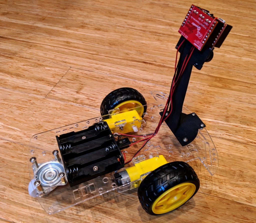
This is the cheapest good computer vision autonomous car you can make — less than $90! It uses the fantastic OpenMV camera, with its easy-to-use software and IDE, as well as a low-cost chassis that is fast enough for student use. It can follow lanes of any color, objects, faces and even other cars. It’s as close to a self-driving Tesla as you’re going to get for less than $100 😉
It’s perfect for student competitions, where a number of cars can be built and raced against each other in an afternoon. NEW BONUS: If you want to move to a more advanced linear-regression code, instructions are here
Parts:
- OpenMV H7 ($65)
- Motor driver shield ($20)
- Robot car chassis ($13) (if that one is unavailable, any one that has two wheels and a castor will do)
- 3D Printed OpenMV mount ($12 from Shapeways. Free if you have your own 3D printer). If you want to modify it, the original files are on TinkerCad here.
- (If you don’t already have this): Some 22-gauge wire to extend the motor and battery wires to the camera ($6).
- Code
Optional:
- Polarizing filter ($10) to block sunlight glare
- Also, a cheaper motor driver board ($7) can be substituted if you don’t mind a slightly less neat installation. For instructions on using that, see this note.
Total: $85 to $120, depending on which options you choose and whether you can 3D print your own parts.
The code is optimized for standard RGB tracks, which can be made with tape.
Instructions:
- 1) Cut two 12″ lengths of black and red wire pairs, and strip 1/4″ from each end. These will be the wires to connect your motors to the OpenMV board.
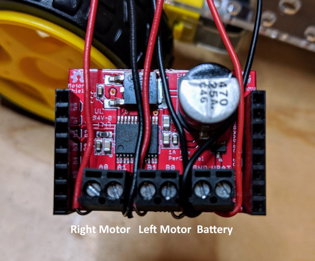
- 2) Assemble the rover kit as per the instructions, soldering the wire you just cut to the motor terminals (for consistency, solder the red wires to the terminals furthest from the chassis and the black wires to the terminals closest to the chassis, as shown in the picture below). We can always switch them at the motor driver side later, but this will make it easier not to get confused). Don’t overtighten the motor mounts; they’re fragile. If you break one, you can 3D print a replacement with this file, buy them from Shapeways here, or just cut it out of 3.5mm plywood.
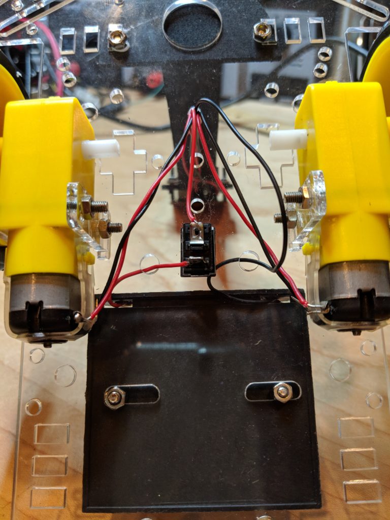
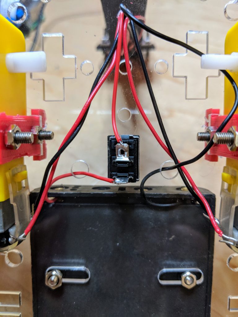
- 3) As for the rocker on/off switch, just snap it into place on the chassis, then snip the red battery wire an inch from the battery case and solder that to one of the switch’s terminals, then solder the rest of the wire to the other terminal as shown here:
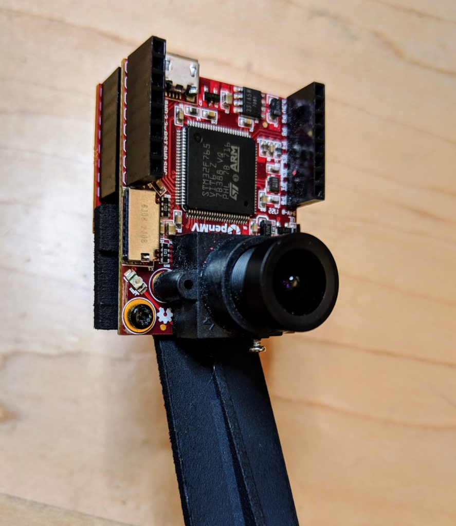
- 4) 3D print (or have printed at Shapeways) the camera mount. Attach it to the chassis with screws as shown in the pictures above.
- 5) Screw the OpenMV camera to the mount as shown:
- 6) Attach the motor and battery wires to the OpenMV motor shield as shown below. Once you’re done, carefully insert it into the connectors at the back of the OpenMV cam.
- 7) Load the code into the OpenMV IDE, plug your USB cable into the OpenMV board and run it while it’s looking at a green object (it defaults to following green, although that’s easy to change to any other color in the IDE). (Make sure your rover is powered on with batteries in). If one of the motors is turning backwards, just swap the wires from that motor going into the motor controller.
- Here’s how to test it and ensure it’s working:
- 8) If the rover tends to turn one way or the other, you can correct the “center” position by modifying the value in this line:
steering_center = 30 # set to your car servo's center point
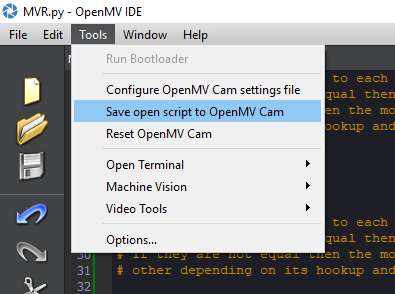
- 9) Once you’re happy with the way the code is working, you can load it so it will start automatically even if a USB cable is not connected by selecting “Save open script to OpenMV Cam” in the Tools menu, as shown:
Code tweaking tips
If you want it to follow a different color, just change this number in the code:
threshold_index = 1
# 0 for red, 1 for green, 2 for blue
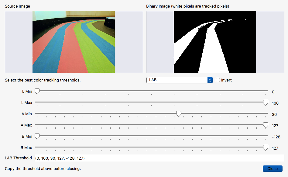
If you want to tune it for another color, or adjust it so it follows the color you’ve selected better for the specific tape and lighting you’ve got, use the IDE’s built-in Threshold Editor (Tools/Machines/Vision/Threshold Editor) and add a threshold set for the color (or replace one of the generic thresholds) that you want in this section of the code:
thresholds = [(0, 100, -1, 127, -25, 127), # generic_red_thresholds
              (0, 100, -87, 18, -128, 33), # generic_green_thresholds
              (0, 100, -128, -10, -128, 51)] # generic_blue_thresholds
# You may pass up to 16 thresholds above. However, it's not really possible to segment any
# scene with 16 thresholds before color thresholds start to overlap heavily.
In the below example, I’ve tuned it to look for red lanes. So I’d copy the “(0,100,30,127,-128,127)” and replace the generic red threshold numbers above with that. Then I’d change the line above that to “threshold_index = 0”, so it would look for the first threshold in the list, which is red (lists are “zero-based”, so they start at zero).
When you’re done, the IDE will show it tracking a color lane like the above (the lowest rectangular “region of interest” — ROI — is weighted highest, with the other two weighted less). You can modify the ROIs by dragging boxes on the screen to show the region you want to identify, and then give it a weighting as show here:
# Each ROI is (x, y, w, h). The line detection algorithm will try to find the
# centroid of the largest blob in each ROI. The x position of the centroids
# will then be averaged with different weights where the most weight is assigned
# to the ROI near the bottom of the image and less to the next ROI and so on.
ROIS = [ # [ROI, weight]
(38,1,90,38, 0.4),
(35,40,109,43,0.2),
(0,79,160,41,0.6)
]
Parts update: OpenMV Cam H7 is now available at https://openmv.io/products/openmv-cam-h7?variant=12409361236062 ($65)
Thanks! Updated..
This is a great project. Thanks to @zlite for the tutorial. We built it this weekend with the OpenMV H7. We used the original MVR.py script with just a couple of minor tweaks. As mentioned above, we needed to adjust our steering_center and set new thresholds for the color of green tape we were using. The threshold editor in the IDE was really intuitive. The only other change we made was with the battery. Since the H7 version of the OpenMV has a little LiPo battery input, we used that with a smaller battery (instead of AAs), which powers both the board and passes through to the motor controller. We posted a little video here: https://youtu.be/BtaL0aD9eyM
Excellent project!
a lot of your links for parts are broken
Thanks. I’ve updated and refreshed the links
Thanks @zlite !
Have you worked with the vehicle to see if you can make it stop when it sees a particular color? Like if it saw red it would stop (like a stop sign).