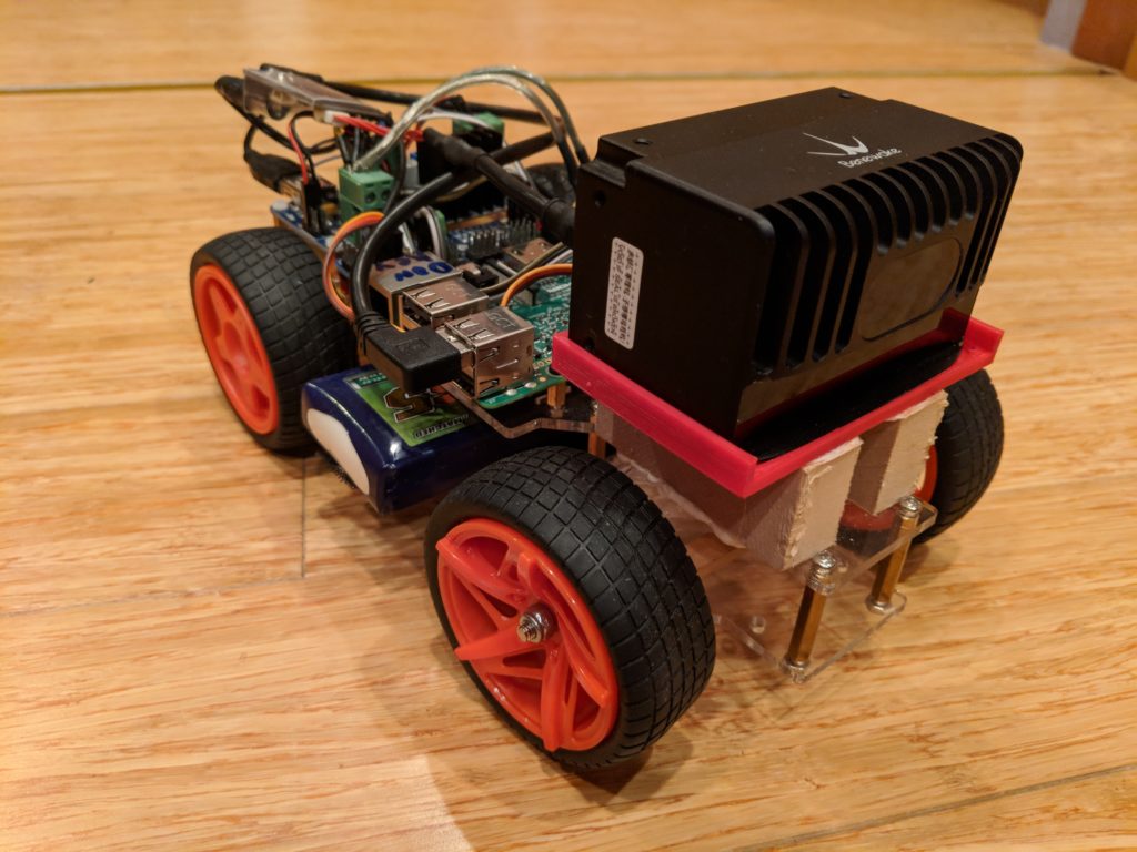
Updated Minimal Viable Racer using latest OpenMV linear regression code

OpenMV continues to be the best and easiest way to get started with DIY Robocars and with the forthcoming H7 version (twice the speed and memory) it’s increasingly capable, too.

Our entry-level code for the “Minimum Viable Racer” uses a basic computer vision technique known as “blob tracking” and treats track lines of a given color as rectangles with a center point, which tells the car how to steer to stay on the line.  This is easy to code but is a pretty blunt instrument, since the rectangles cover a large area of track and if that includes a curve the center point is really very approximate.

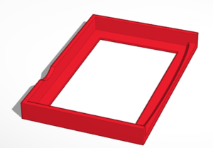
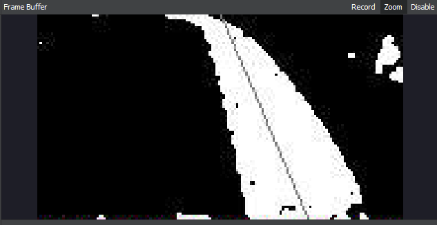
A more sophisticated computer vision approach is to do linear regression on all the detected points of the track line, which provides a more reliable “racing line” that ensures that the car is staying closer to the actual line on the road (shown below). This is the techniques used by OpenMV-based Donkeycar, which has reliably placed in the top five in DIY Robocar races.

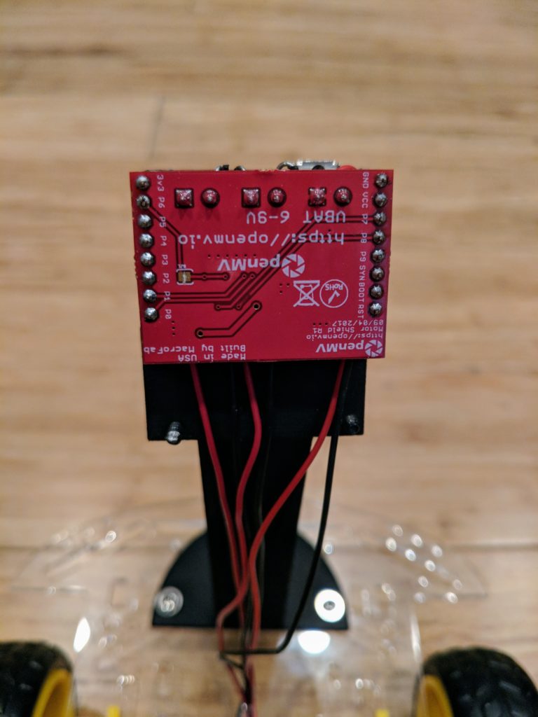
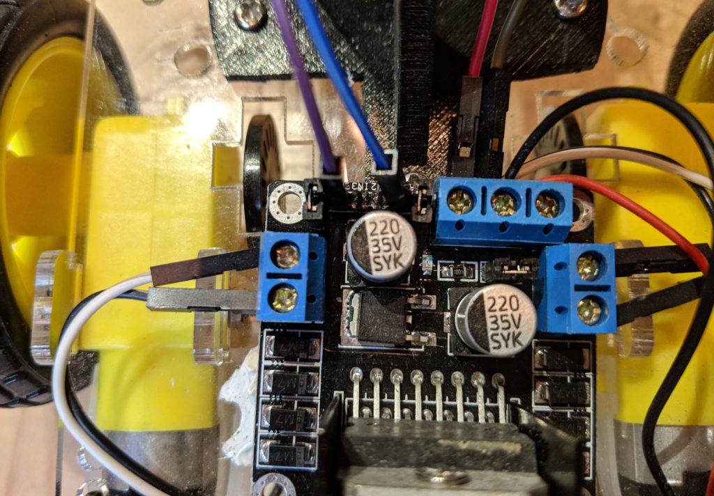
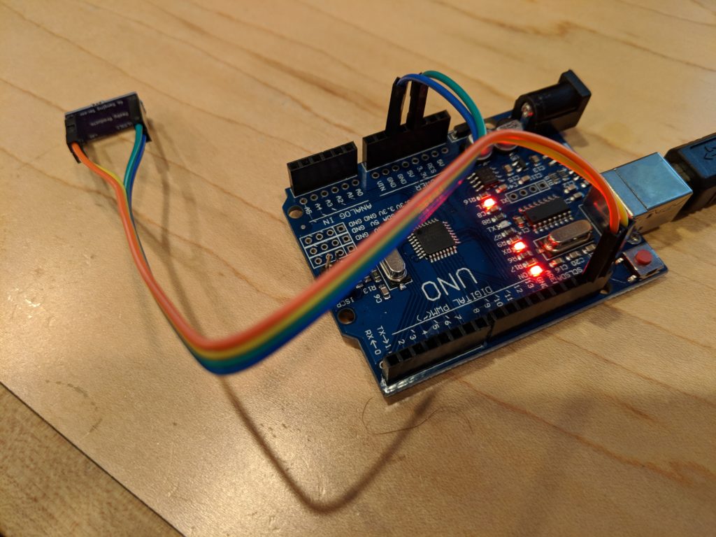
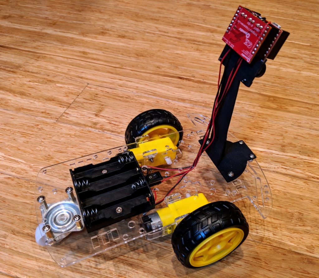
I’ve now created a version of that code that runs on the Minimum Viable Racer, too, using the stock OpenMV Motor Shield. No changes to the hardware are needed.

Get the code here

Notes: 

It defaults to following a yellow line. To tell it to follow a different color, change this line to the color thresholds that works for your line, using the IDE’s Tools/Machine Vision/Threshold Editor

  1. Ensure “BINARY_VIEW = False”, so you can see the actual colors of the track and not just the black-and-white results. You can switch this to “True” when you’re done if you want to see how well it’s working, which will generate an image like the above.
  2. Change “COLOR_THRESHOLDS = [( 94, 100, -27, 1, 20, 127)]” to the correct thresholds for the colors of the line you want to track.

These are some other things you can tweak:

cruise_speed = 50
steering_direction = 1 # use this to reverse the steering if your car goes in the wrong direction
steering_gain = 1.0 # calibration for your car's steering sensitivity
steering_center = 0 # set to your car's steering center point


First impressions of Slamtec SDP Mini Lidar/SLAM development rover

I’ve had a chance to try out the new Slamtec SDP Mini development platform, from the maker of the popular RP-series low-cost Lidar scanners, and it’s nothing short of amazing. For $499, you get a RP-Lidar A2 2D lidar (which normally costs $320 just by itself), a Slamware hardware SLAM processing module along with a carrier board with wifi (another $300+ package), and a very competent rover chassis with wheel encoders.

Putting aside the value of nearly $1,000 worth of gear for half that price, what’s amazing about the SDP Mini is that it works. SLAM is notoriously hard and usually requires a full PC worth of computer power and complex software like ROS (although you can roll your own for less than $200 if you’re willing to settle for lower resolution, as described in the post here).

What the Slamtec SDP Mini does is combine a capable 8m-range, 8000-samples/second 2D Lidar unit with the necessary hardware to interpret it and turn it into an accurate map of the space its in. It builds the map as it drives around and localizes itself in that, thus the name: Simultaneous Location and Mapping (SLAM).

The magic all happens on the Slamware Core module, which is a single-board computer + IMU runing Slamtec’s SLAM software. It fits on a carrier board, which adds Wifi, motor controllers for the robot and connectors for wheel encoders and other sensors.

Most important is the SDK, which supports Android, iOS, Windows and Linux. Much of the documentation is still in Chinese, but Chrome can auto-translate it quite well into English. Along with all the usual Lidar functions, the SDK has full support for maps, pathfinding, wall-avoidance and encoder reading. This is an absolute nightmare in ROS (five Linux terminal windows, if you can even get it running), but is super easy with Slamware.

Here’s a sample of navigation, using the Android app (which communicates with the SDP Mini via Wifi). (2020 Update: Slamtec has now removed the RoboHome app and replaced it with the similar RoboStudio, which is available as both Windows and Android apps. The Android app on their website won’t run on Android 11 in my testing, but they do have a more recent version that will. It’s here.) It automatically made a map of my room in a few seconds and then can navigate to any point in the room with just a click.

Even cooler, you can create “virtual walls” by just drawing a line in the app. Then, when you tell it to navigate, it will find a path that avoids the wall.

Slamtec also has a Roomba-style larger SDP platform (shown below) that does the same thing, but can carry larger payloads and also includes automatic return to charging base and bumpers/sensors to avoid obstacles and stairs. It’s only available via special order now, but will soon be available more broadly at a price to be announced. Overall, the Slamtec range is super impressive.  If you want SLAM, look to China!

Lidar SLAM without ROS for less than $200

Until recently, if you wanted to do SLAM (Simultaneous Location and Mapping) with LIDAR without a huge amount of coding work, you really only had one choice: ROS on a beefy computer.

This had two problems: 1) beefy computer (cost, size) 2) ROS (complexity, overhead, crazy difficult UI)

Good news: you don’t need either of them anymore. 

Simon Levy has recently updated his very efficient BreezySLAM python code (paper describing it is here) to support the new generation of cheap and powerful LIDAR and single-board computers, including:

  • Slamtech series of LIDARs (A1, A2, A3) using the RPLidar Python library. I recommend the A1, which is just $99 and has a range of 12m with 8,000 samples per second. Run the rpslam.py example see it working
  • Single-board computers. Although it will work on a Raspberry Pi 3, I recommend the Odroid XU4, which is just $80 and easily twice as fast and otherwise works the same under Linux
  • Mini PCs. Atom-based x86 mini PCs cost just a little more than single-board computers and are easier to expand. BreezySLAM has been tested on this one ($116, including Windows, which you should ignore and run Linux instead!) and works fine.
  • Alternatively, get a full-fledged Intel NUC, which is more expensive but can run BreezySLAM at higher resolution with lots of processing overhead to do other things like machine learning and computer vision. If you get this one ($339), you’ll need memory and storage 
  • It will of course also work on any PC running Linux

If you combine an Odroid and the RP-Lidar A1, you’ve got a powerful full Lidar SLAM solution for less than $200!

A few notes:

  • Follow the BreezySLAM instructions here. If you’re using a RP Lidar device (recommended!) don’t forget to install the RPLidar library first: “sudo pip3 install rplidar”
  • Depending on the speed of your computer, you may need to sample fewer data points per update, which you can do by modifying the “MIN_SAMPLES” line in the code. For example, on the Atom Mini PC above I can only get 195 samples before I get the “no map screen of death” shown here:

  • On the Intel NUC, I can get to 210 points per pass.
  • On the Odroid I can get 200 points
  • On the Atom Mini PC, I can get 195
  • On the Raspberry Pi 3, I can only get 75 at one update/sec, with lots of artifacts, so not really useful yet.

My recommendation: go with the RP Lidar A1 and the Odroid. That’s less than $200 and it works great.


Comparing three low-cost integrated computer vision boards for autonomous cars


(Above, from left: Pixy 2, Jevois, OpenMV)

Computer vision used to be hard. No more. Now you can run OpenCV on a RaspberryPi, or even better use a dedicated computer vision camera/computer combo that costs less than $60. It’s kind of amazing, and perfect for small and cheap autonomous cars.

I’ve tested three of these camera/CV combo products with a DIY Robocar as the use case.

Here’s a quick review of the three and how they compare. I’ve previously compared Jevois and OpenMV, but both have improved since then — Jevois on the software side, and OpenMV on both the software and the hardware side with the forthcoming H7.  But now Charmed Labs has come out with the Pixy 2, which adds line following along with much improved hardware and software, so I’m expanding the comparisons.

For the OpenMV car, I tested the “Minimum Racer” configuration. For the other two, I used the Adafruit rover chassis, an Arduino and a motor driver board. My code for the Pixy 2 with the Adafruit motor driver shield is here 

Winner: OpenMV M7/H7

Why: Best IDE, copious I/O and shields mean no extra parts to drive a car, easy to program. Still the one to beat, and with the forthcoming H7 (to be launched via Kickstarter in September) it will have the computing power to do amazing frame rates and neural networks.

Fun Feature: The way it handles AprilTags (like QR codes, but super fast for robots to recognize) is miraculous. It can recognize them from 20 feet away when integrated with blob tracking.

Second Place: Pixy 2

Why: This is a big improvement over the original Pixy, which could just do color blob tracking. The new version has a fun line-following app and good Arduino/RaspberryPi integration. But it’s not really programmable and you’re limited to the four apps already loaded. And you need to add an Arduino and motor driver shield to drive a car. It doesn’t really do anything that OpenMV doesn’t do better.

Fun Feature:  The three white LEDs make for great headlights!

Third Place: Jevois

Why: The Jevois hardware is amazing, but it has been hamstrung by overly complex software (no IDE)  (UPDATE 6/20: It now has one and it looks great) and no I/O. The I/O problem remains, but the software has been much improved and now includes some good TensorFlow deep learning demos and some basic Linux command line support. But like the Pixy 2, to drive a car it needs an Arduino (or equivalent) and motor driver board to be connected.

Fun Feature: It can recognize 1,000 objects out of the box thanks to TensorFlow.


Here’s how they compare in features

OpenMV M7/H7Pixy 2Jevois
Cost$65 (M7), $59 (H7, coming in Sept)$59$59
IDEFull-featured, cross platform (Mac, Win, Linux)Just a viewer appFull-featured, cross platform (Mac, Win, Linux)
LanguageMicropythonNot really programmablePython
Processing power (QVGA)60 FPS (M7)
120 FPS (H7)
60 FPS60 FPS
Memory0.5MB RAM, 2 MB Flash (M7)
1MB RAM, 2MB Flash (H7}
N/A256MB
Add-on boards availableLots: servo, Wifi, motor controller, LCDNoneNone
Interchangeable lensesYesNoNo
Interchangeable sensorsNo (M7)
Yes (H7)
NoYes
Sample apps~30 covering wide range including deep learning4 (color and line tracking). No deep learning~30 covering wide range including deep learning
I/OUSB, SPI, CAN, I2C, 3x PWM, Serial, ADC, DAC, USB, SPI, 2x PWMUSB
SD CardYesNo Yes
Lights2x IR3x WhiteNo
Cost to make a car$100 (OpenMV + motor shield + car)$115 (Pixy 2 + Arduino + Adafruit Motor Shield + car)$115 (Jevois, + Arduino + Adafruit Motor Shield + car)

Using a cheaper motor driver with the Minimum Rover

If you want to use a cheaper motor driver board ($7) for the OpenMV-based “Minimum Rover“, here’s how to hook it up:

You’ll need some female-to-female hookup wires ($6).

First, plug four wires into the OpenMV’s GND, VIN, P7 and P8 pins as shown

Then connect those four wires to the motor controllers as shown in the picture below:

  • P7 goes in In1
  • P8 goes to In4
  • GND goes to GND
  • VIN goes to +5V

Then connect the motor wires to the terminals on each side of the motor controller, right motor wires to right side terminals, and left side motor wires to left side terminals, as shown. The wires from the battery go to the GND and 12V terminals (cut off the connector and put the bare wire in the terminal and screw it down).


The code requires no modification to use this motor controller. It should work exactly the same as the OpenMV motor controller shield.


Demo of Benwake CE30-A on a DIY Robocar

After my first hands-on experiments with the new Benwake CE30-A solid state LIDAR (the version that generate an obstacle position rather than a point cloud), I thought I’d see if it was sufficient to drive a car through an obstacle field. It is. Above is my first effort at doing that, using a commonly-available Sunfounder RaspberryPi-based robocar.

My RaspberryPi Python code is here.

A few lessons:

  1. You can run the Benwake CE30-A with the same 7.4v battery pack that you would use to drive the car. (It says it wants 12v but it works fine with less than that).
  2. If you want to create a shorter cable. the connectors used by the CAN-to-USB converter board are JST-GH 1.25mm 4-pin connectors. You can buy them here.
  3. You can 3D print a mount for the LIDAR. I’ve posted a 3D-printable file here.  Just raise it above the steering servo with some blocks of wood as shown here:


First hands-on impressions of new ST laser distance sensor

A year after announcing it, ST has finally released the new version of its tiny laser time-of-flight distance sensor with twice the range of the previous version. Called the VL53L1 (the previous version was the VL53L0), it’s available in chip form for $5 and in a breakout board from Tindie for $19 or a nicer one with connectors and mounting holes from Sparkfun for $25. These are chips originally designed for proximity sensors for smartphones (that’s how the phones can tell if you’re holding them up to your ear and dim/turn off the screen), and are very reliable. The claimed range is up to 4m indoors (up from 2m with the previous version), and since it’s a laser it has a very narrow beam (unlike sonar) and is appropriate for obstacle detection in DIY Robocars.

Sparkfun has just release an Arduino library for it, and the example code works well with both the Sparkfun and Tindie versions. If you want to try it, just connect either breakout boards SCL and SDA pins to the Arduino SCL and SDA pins and the voltage to the Arduino’s 3.3v pin and GND, as shown here:

In my testing so far, I’m only getting reliable reading up to 2.3m (7.5 feet), but there are some special high-power settings that you can enable, although they are not yet supported in the Sparkfun library.  That said, that’s more than enough for 1/10th scale robocars indoors, and is far more accurate than the broad-beam sonar or IR sensors that would otherwise be used for low-cost obstacle detection.

Outdoors, it’s pretty much useless, especially in bright sunlight. Expect no more than 1m outdoors even in the shade, so I’d recommend a different sensor such as sonar or a somewhat more expensive 1D lidar like the TFMini ($40) for that.

First impressions of Benewake CE30 solid-state LIDAR

The era of small, cheap (sub-$1,000) Lidar is upon us, but it’s still a bit in its teething stage. In this post, I’ll give some initial hands-on impressions of one of the first solid-state 3D (actually closer to 2.5D) Lidars to hit the market, the Benewake CE30 series, which has just been released.

Unlike the other Lidars I’ve been using, such as the RP-Lidar A2/A3 series and (now discontinued) Scanse Sweep, which are rotating 2D Lidars (just viewing a thin horizontal disc around themselves), the CE30 has no moving parts and has both horizontal and (limited) vertical scanning (132° horizontal and 9° vertical), as well as an impressive 4m-30m range (depending on which version you get) as well as an excellent 20Hz refresh rate.  That’s perfect for small autonomous cars like ours — solid state means nothing to break in a crash, and having a vertical as well a horizontal sweep means that we can see obstacles from ground level to above the car.

Initial testing confirms the 4m range, dropping to about 3.5m in bright sunlight outdoors, which is quite good.

Official pricing ranges from less than $1,000 to $1,500, depending on the version, but at volume they’ll be available for $400-$500. If you want to buy one now in single units, you can find them on Roboshop: the CE30-A (USB version) is currently $999, the CE30-C (ethernet version) is $1,195 and the CE30-D (long range) is $1,499.

Here’s a table that shows how they compare:

CE30-ACE30-CCE30-D
Max range4m4m30m
InterfaceUSB/CANEthernetEthernet
NotesOnly obstacle detection Point cloud, no built-in obstacle detectionPoint cloud. 4mm larger in width and height
Typical single-unit price$800$1,000$1,500

Size-wise, it’s about the same size as the 2D Lidars, which is to say just right for our cars. (It’s shown above mounted on a Donkeycar, next to a Scanse Sweep for comparison).

I’ve posted a mount for it here, which you can 3D print for your car:


Here’s a screen-capture of the sort of data it provides (me in my workshop waving my arms like a dork). The top window is the uncorrected depth map and the bottom window is a top-down view.

The software support is still pretty minimalistic: a Windows demo program (shown above) and C++ libraries for Windows and Linux (including ROS). The Linux library is designed for x86 computers and won’t compile on a RaspberryPi (which is ARM-based) yet, but Benewake says that compatibility is coming soon. Stay tuned while I wait for that — I’m particularly interested in the built-in obstacle detection mode of the CE30-A, but want to run it on the RPi.

[Update: CE30-C Python code that runs on RaspberryPi is here. CE30-A Python code is here]

One of the tricky things if you’re using the CE30-C (ethernet interface) with a RaspberryPi is figuring out how to talk to the Lidar on Ethernet at the same time you’re connected to the Internet (or another network) over Wifi. After a lot of research and asking around, I finally figured it out. Raspian (the RaspberryPi Linux distro) has been changing its networking configuration process with each version, which makes it hard to find reliable tutorials online, but for the latest version (Raspian Stretch), edit your etc/dhcpcd.conf file to include these two lines:

This will assign your Ethernet port to the CE30, while leaving your Wifi adapter free to connect to your regular Wifi network.

Needless to say, if you opt for the USB version (CE30-A) you don’t need to deal with this — it just shows up as a serial port.

Finally, here’s Benewake’s promotional video that shows what these Lidar’s are really designed for.

Next post will be after I get the software up and running in an autonomous car stack. But so far so good!

Current performance of the DIY Robocars teams

The semi-monthly Oakland DIY Robocars races have now moved next door to the American Steel Poplar Gallery, which has a shiny, slippery polished concrete floor, so we’ve recalculated the performance metrics just to compare races on that track (as opposed to the rougher track at Pacific Pipe next door).  The data from the past four races are above (just the top five in each race), and you can see some clear trends:

1) An average race-to-race improvement of top finisher of about 10%:

2) Less of a gap between the top 5 cars, suggesting that people are starting to dial things in better

3) A machine learning car (Carputer) is currently in first place, but the next three are computer vision (most of them using OpenMV). That suggests that ML is potentially better, but harder to get working well, which agrees with our real-world experience.

4) At this pace, the autonomous cars will beat the best human time in the next 2-4 months. It’s worth noting we don’t actually know what the “best human time” is for this track because we don’t know any humans who can drive RC cars particularly well, so this is a guess based on the best driving we can do. Since the ML cars use “behavioral cloning” (the human drives while the car records the data, then the car attempts to do the same at 1.3-1.5x speed), the ML cars that use this technique are by definition faster than their masters. But that doesn’t mean that they could beat any human.

5) The really fun part is the “all cars demolition derby” at the end. Pay particular attention to the tiny car on the outside, which is a Minimum Viable Racer built by Eric. He was a good sport about following the Fight Club rules (“If this is your first night, you must race”) and we promised him we’d help him rebuild it if it got crushed. The race isn’t over until Eric is done!